Communication Diagram Explained
Create a Communication Diagram Online Free Free Download Free Download Free Download Free Download1. What Is Communication Diagram in UML?
UML Communication Diagrams, previously known as collaboration diagrams are a type of behavioural diagram that shows the interactions that take place between objects in a piece of software or system. This type of diagram emphasizes the messages exchanged between objects. Communication diagrams are best used when one use case has multiple scenarios that need depicting.
2. Applications Scenarios of UML Communication Diagram
UML Communication Diagrams, previously known as collaboration diagrams are a type of behavioural diagram that shows the interactions that take place between objects in a piece of software or system. This type of diagram emphasizes the messages exchanged between objects. Communication diagrams are best used when one use case has multiple scenarios that need depicting.
- Show the passing of messages between objects in a system or piece of software
- Depicting the interactions between objects
- Visualize how messages are sent and received between objects, as well as the consequences
3. Communication Diagrams vs Sequence Diagrams
Communication diagrams are often compared to sequence diagrams - both also depict the interaction of objects, and even share the same symbols and notation. But what separates the two of them?
- Sequence diagrams as the name suggests, focus on the order of events and interactions. There is greater emphasis on the timing of operations, as well as the sequential logic behind it.
- Communication diagrams better show the relationship between objects. It offers a far more holistic view of a system. Rather than just knowing what happens and when, communication diagrams afford the user the benefit of viewing how different parts of a system collaborate to work together.
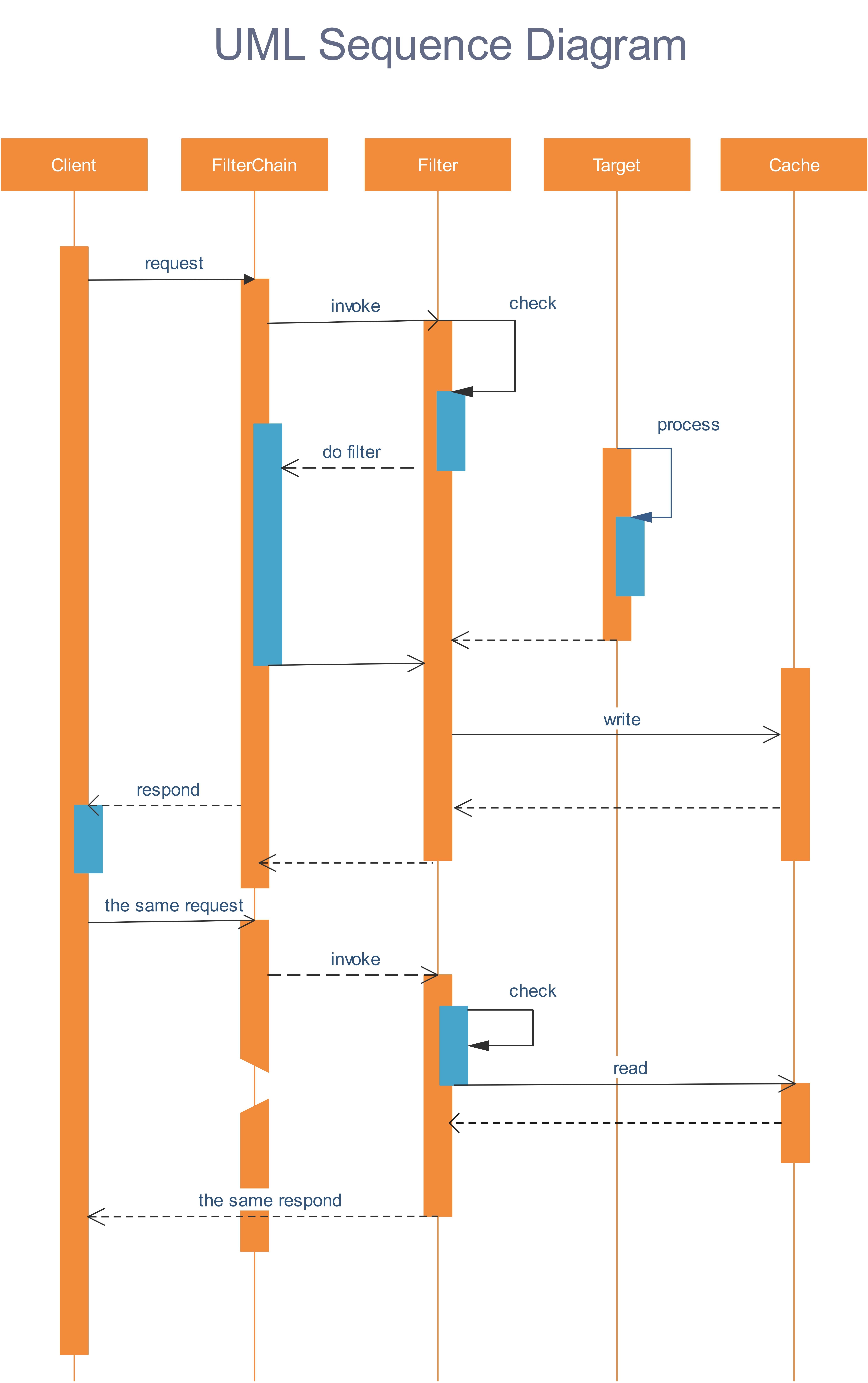
Sequence diagram template - EdrawMax
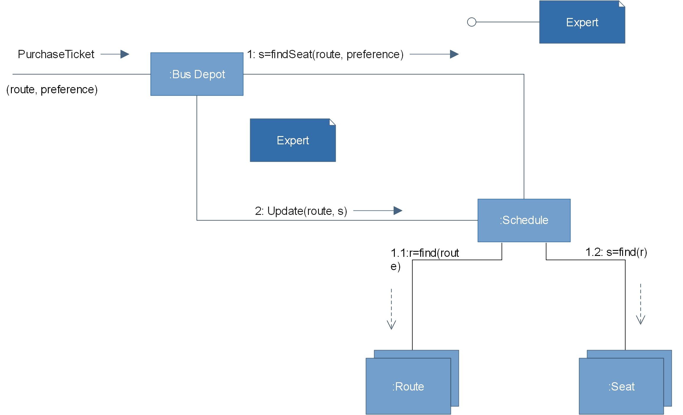
Communication diagram - EdrawMax
4. Communication Diagram Symbols
You can find some commonly used symbols and components of communication diagrams below.
- OBJECTS
- LINK
- MESSAGES
- Synchronous message: a sender transmits a message, and must wait for a response before continuing. This is shown by a straight line and a solid arrowhead.
- Asynchronous message: a sender does not need to wait for a response before proceeding. This is shown by a straight line and a lined arrowhead.
- Sequence of messages: Typically, messages will have a number and description next to them. The number determines the order in which messages should be read.

Objects can be classed as either a supplier or a client. Suppliers call the function that supplies the message. Clients send the message to the supplier, who receives it.

Link: a straight line connecting two objects indicates a relationship between them. The two objects are able to send messages to each other.


5. How To Create Communication Diagrams Online
EdrawMax’s intuitive software allows you to create your own communication diagrams. Whether it’s a basic or complex one, follow this outline to create one that fits your needs.
- In your browser, visit https://www.edrawmax.com/online/ to access the online version, or download the desktop version at https://www.edrawsoft.com/download-edrawmax.html
-
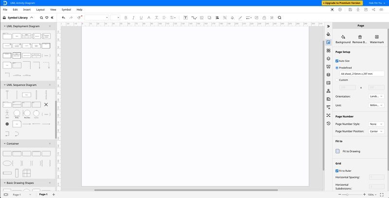
In the white sidebar, click on Software Development. Then, click on the UML Modelling box that appears near the top of the screen.
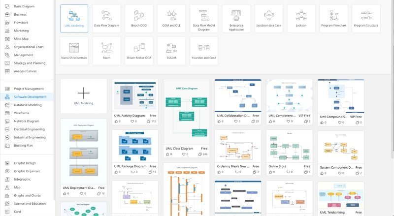
- Choose a template, or click on the UML Modelling box with the “ + ” to open a new document. Note that in Edraw Max’s software, the communication diagram template is titled “UML Collaboration Diagram example”.
- The symbol library can be found to the left of the screen. Scroll down further to find more UML-related symbols.
- Simply drag the components you need from the symbol library onto the blank document to start creating. Each element can be moved, re-sized, or customized to fit your needs.
6. Communication Diagram Examples
Here are examples of a communication diagram drawn in EdrawMax.
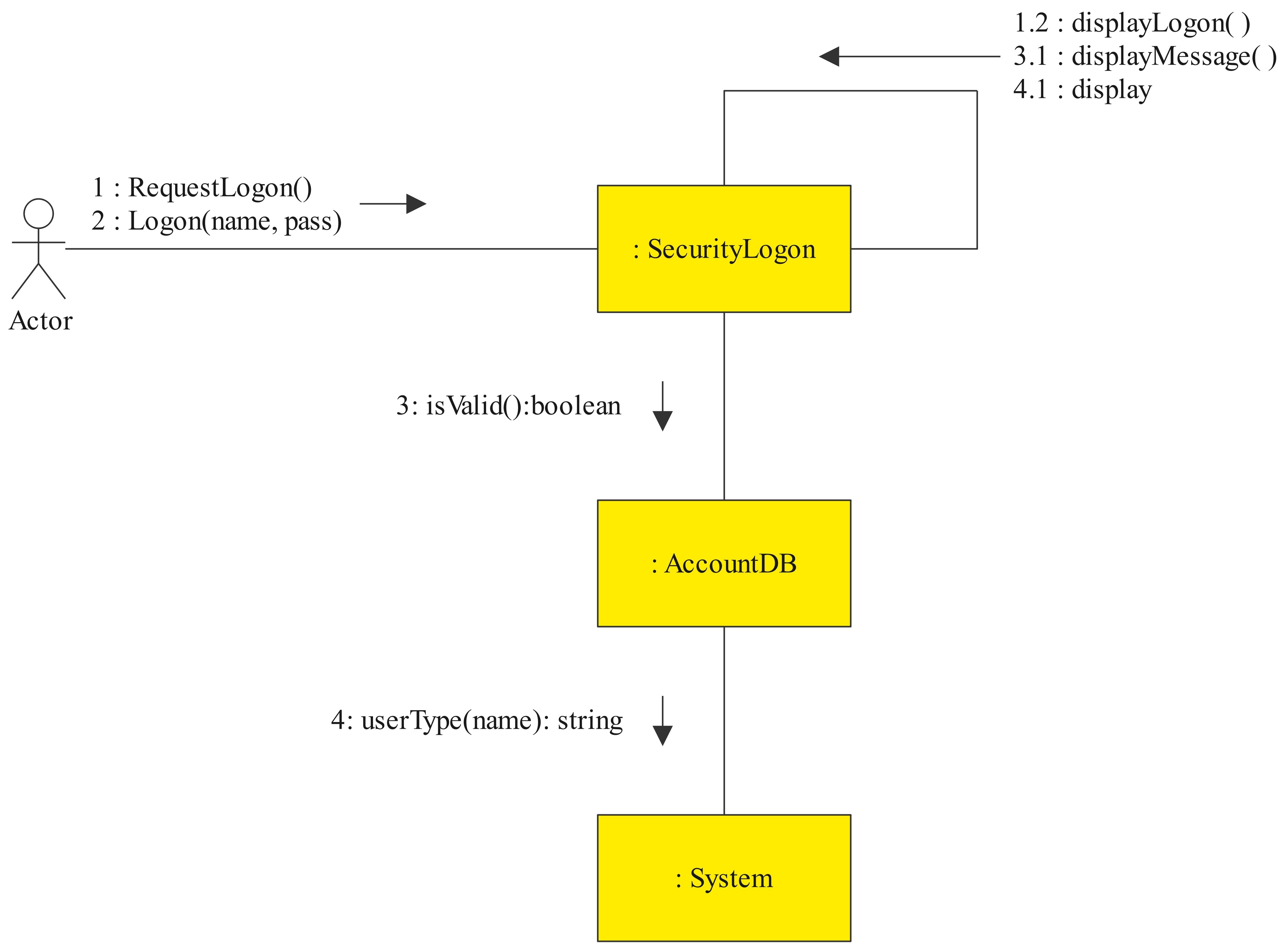
UML Communication Diagram 1: User login
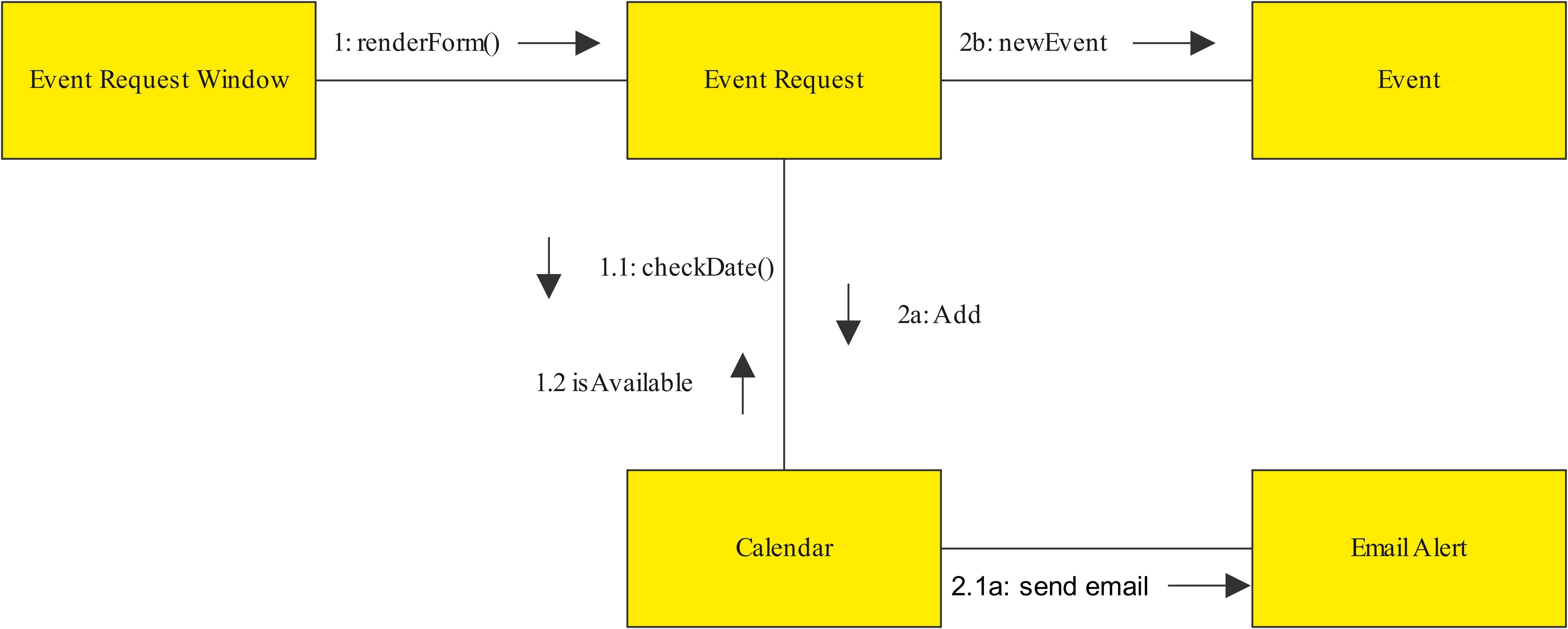
UML Communication Diagram 2: adding an event to your calenda
7. Summary
Communication diagrams show much more than just a sequence of events. Just as with any piece of software, there will be many smaller parts interacting with one another, sometimes concurrently. Using a communication diagram to model your system allows you to break down a series of complex interactions in said system.
Business users, as well as software and web developers, have embraced communication diagrams as a vital way of visualizing the various interactions and communications in a system. Don’t miss out - try out EdrawMax and create your own communication diagram now!


