P&ID Symbols and Meanings
1. What Are P&ID Symbols
P&ID diagrams are made with specific and standard shapes and symbols. As this diagram covers many types of diagrams as the variety in industries is vast, many symbols are required. These diagrams provide a map for the engineering system's design which is helpful to problem identification and solving. The most popular instruments are actuators, equipment, flow elements, instrumentation, piping fittings, valves, and more. P&ID symbols are industry-standard symbols, including instruments, equipment, heat exchangers, vessels, pipe, motors, and interconnecting lines.
2. P&ID Symbols Explained
P&ID symbols are categorized according to their functions and industrial uses. The major categories are piping, instrumentation, pumps, valves, vessels, heat exchangers, compressors, and equipment.
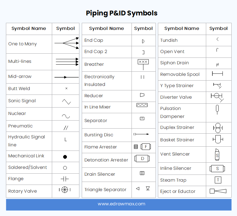
2.1 Piping P&ID Symbols
Piping P&ID symbols represent the equipment that transports fluid substances. There are multiple types of pipes that make them eligible for a separate category. It can be simple, multi-line, separators, connectors, end caps, flanges, reducers, and coupling. The list of piping symbols is as follows.
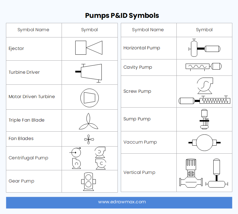
2.2 Pumps P&ID Symbols
Pumps are an essential part of the majority of industrial plants that need pumps, which can be used for suction, compression, moving fluid, and also for pressure control. There are many p and id symbols for pumps. Here is a list.
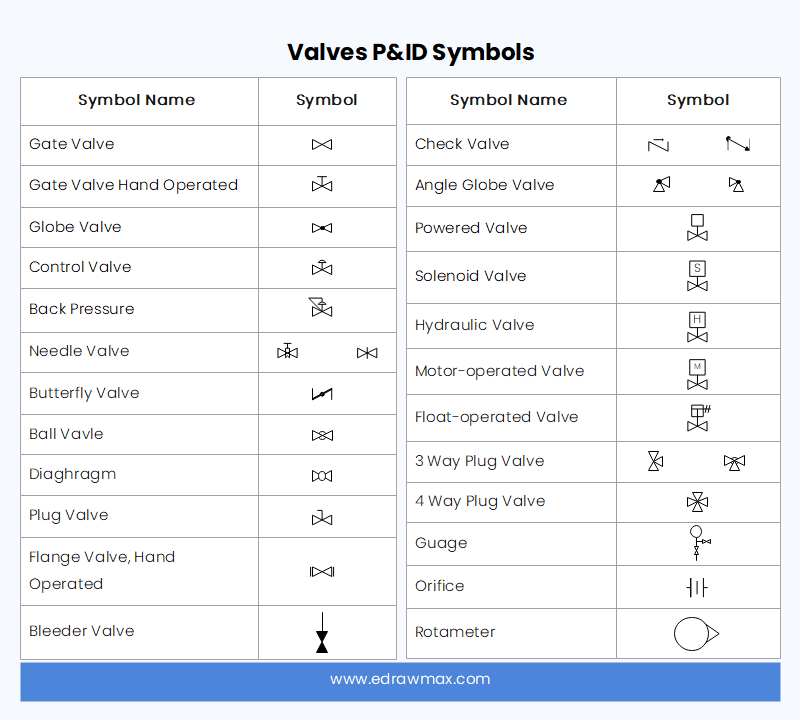
2.3 Valves P&ID Symbols
Valves in the engineering design are for control flow. The two categories are Actuators and Self-Regulated Relief Valves. The specific symbols are:
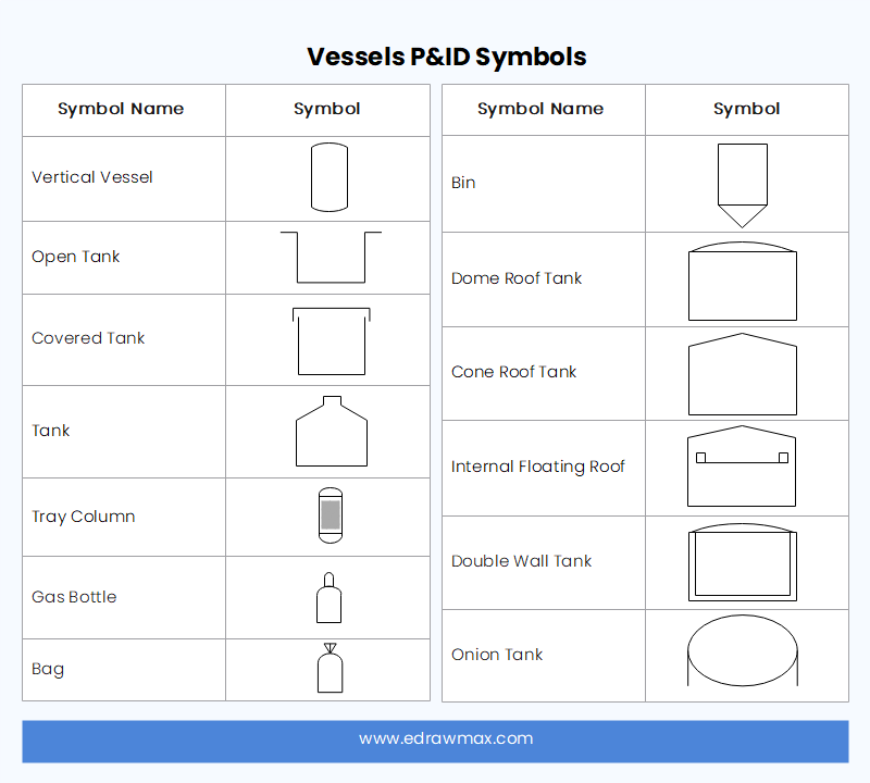
2.4 Vessels P&ID Symbols
A vessel is used to show containers to store fluids. The larger vessels P&ID symbol group includes tanks, cylinders, columns, bags, and others.
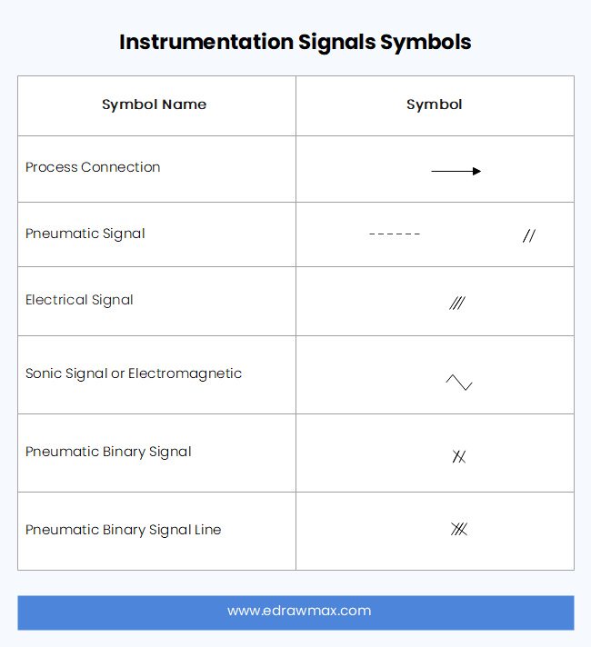
2.5 P&ID Instrumentation Symbols
Instrumentation symbols in a P&ID are standardized to ensure consistent control and automation. It helps in the identification of the part and broad base understanding of the process. Common instrumentation symbols are meters, transmitters, sensors, indicators, and other measurements and recordings.
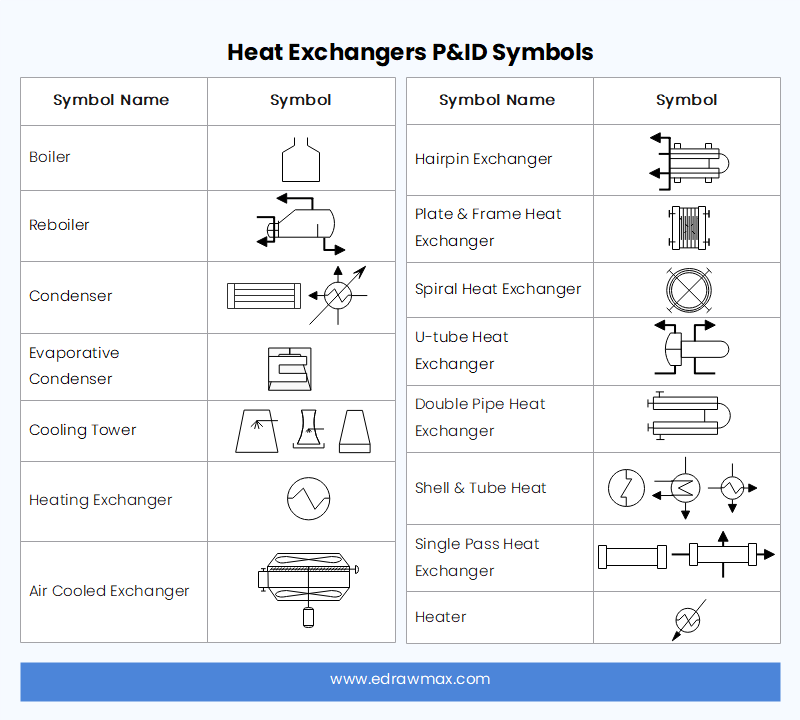
2.6 Heat Exchangers P&ID Symbols
A heat exchanger transfers heat between different surfaces, fluids, mediums, or areas. These devices can be used in both cooling and heating processes. The symbols include boilers, condensers, and other heat exchanging devices.
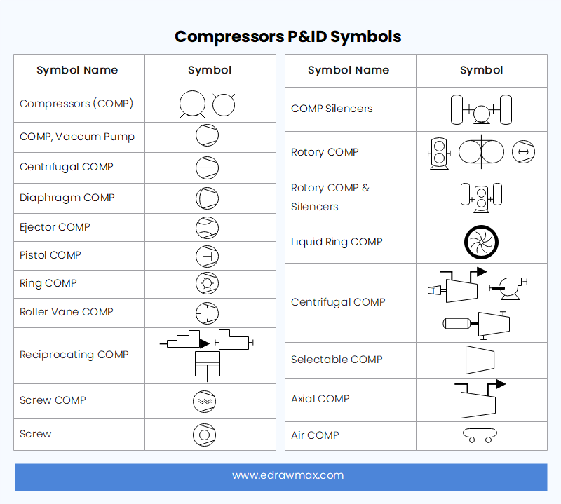
2.7 Compressors P&ID Symbols
Compressors and blowers move air or gas through an operational process. Compressors operate at a high pressure-to-volume ratio, while blowers operate at a low-pressure ratio. The list of compressor p and id symbols is listed below.
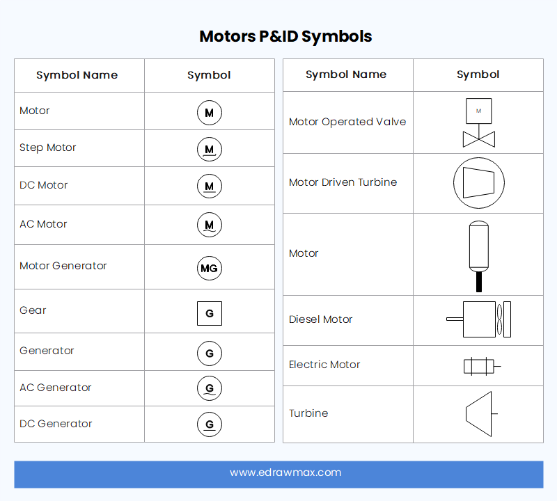
2.8 Motors P&ID Symbols
Motors are so important that you will even find them in toy cars. So no industrial process model can be made without motors. Motors are available in many different variants. Generators are also included in this category. Common motor and generator P&ID symbols are:
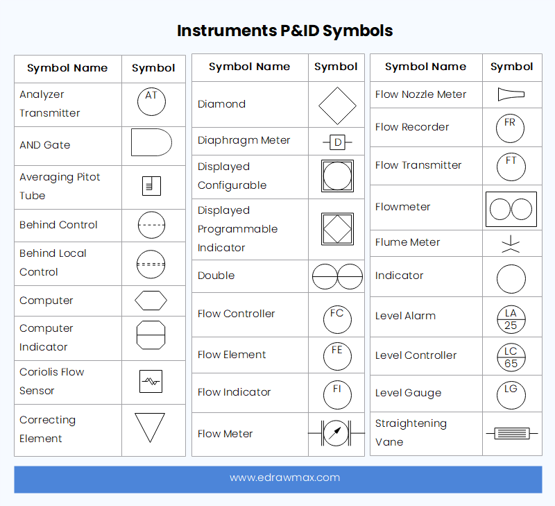
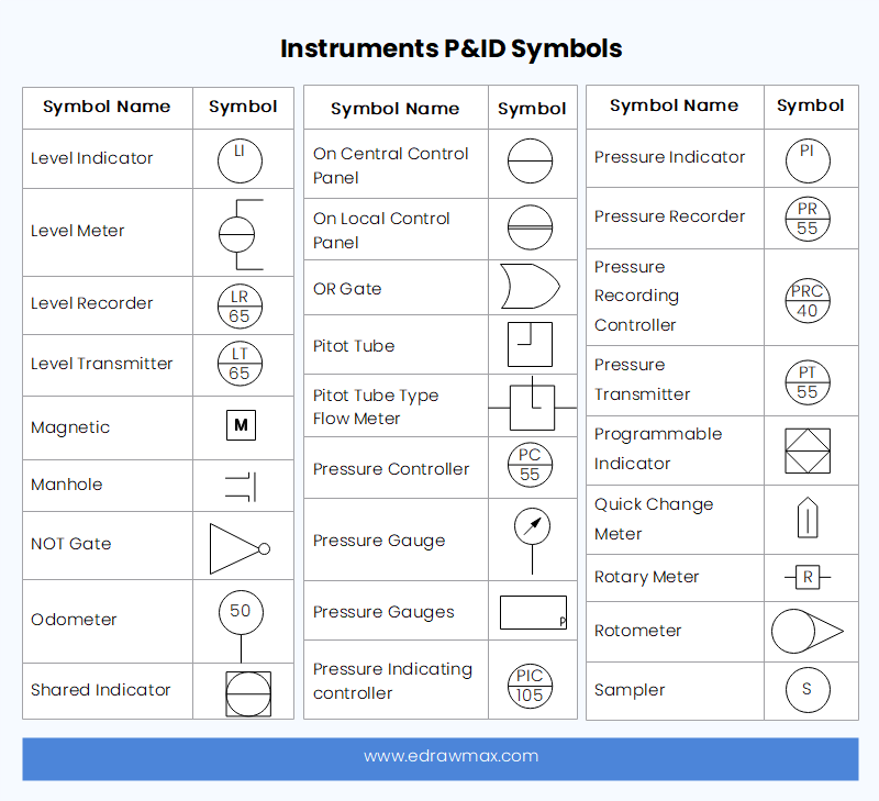
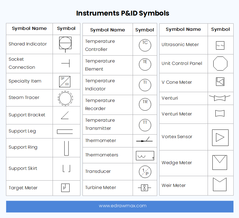
2.9 Instruments P&ID Symbols
An instrument is a device that measures and controls different parameters such as flow, temperature, angle, or pressure. This broad category includes indicators, transmitters, recordings, controllers, and elements.
There is a bubble mark on each instrument that represents the proper specification of the instrument. How to read these labels? These labels are divided into three parts.
1. A horizontal line. It can be found in three types.
- A single horizontal line shows that the instrument is located on the main control panel and available to the panel operator.
- No horizontal line represents it is installed in the field and access to field operators.
- A dashed horizontal line is used when the instrument is inaccessible in the field. It can be hidden or password-protected on the control system.
2. The label is a combination of three letters that shows the parameter being measured, what the instrument does, and the instrument. So a label "FIC" shows;
- F -> The parameter being measured is Flow here.
- I -> What the instrument does, it is Indicator here.
- C-> Instrument, it is Controller here.
3. The third figure that comes under the horizontal line is the Control loop.

P&ID Symbols Abbreviations
| Analyzer Element (Chemical Composition) | AE |
| Air Operated Valves | AOV |
| Burner Element (flame detector) | BE |
| Conductivity Recorder | CR |
| Differential Pressure | DP |
| Density Transmitter | DT |
| Flow Controller | FC |
| Flow Control Valve | FCV |
| Flow Element | FE |
| Flow Sight Glass | FG |
| Flow Hand Control (manual) | FHC |
| Hand Switch in Flow Loop | FHS |
| Flow Indicator | FI |
| Flow Indicating Controller | FIC |
| Flow Meter | FM |
| Flow Quantity Recorder | FQR |
| Flow Quantity Indicator | FQI |
| Flow Recorder | FR |
| Flow Recorder Controller | FRC |
| Flow Switch | FS |
| Flow Transmitter | FT |
| Flow Transducer | FTD |
| Hand Operated Control Valve | HCV |
| Hand Switch | HS |
| Level Controller | LC |
| Level Control Valve | LCV |
| Level Gage Glass | LG |
| Level Hand Control (manual) | LHC |
| Level Indicator | LI |
| Level Indicating Controller | LIC |
| Level Recorder | LR |
| Level Switch | LS |
| Level Transmitter | LT |
| Level Transducer | LTD |
| Motor Operated Valve | MOV |
| Motion Transmitter | MT |
| Pressure Alarm | PA |
| Pressure Controller | PC |
| Pressure Control Valve | PCV |
| Differential Pressure Indicator | PDI |
| Ph Transmitter | PHT |
| Pressure Indicator | PI |
| Press. Indicating Controller | PIC |
| Press. Indicating Transmitter | PIT |
| Pressure Recorder | PR |
| Pressure Switch | PS |
| Pressure Transmitter | PT |
| Pressure Transducer | PTD |
| Pressure Relief Valve | PZV |
| Temp. Indicating Controller | TIC |
| Temp. Recorder | TR |
| Steam Trap or Airvent | TRAP |
| Temp. Switch | TS |
| Temp. Switch Alarm | TSA |
| Temp. Transmitter | TT |
| Temp. Transducer | TTD |
| Thermowell | TW |
| Weight Measuring Element | WE |
| Annunciator | XA |
| Vibration Detector | XVE |
| Vibration Switch | XVS |
4. P&ID Symbols PDF
We have created a printable p&id symbols PDF file that you can download and print if you wish to have a quick reference to the p&id symbols list. You can download the file by clicking on the image below.
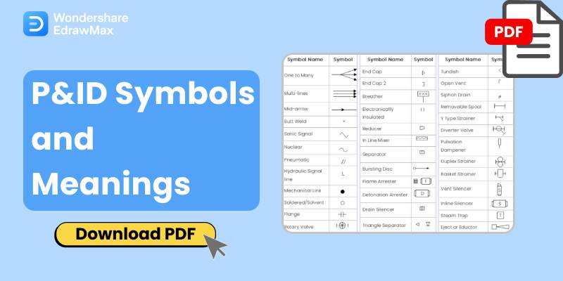
Click the image to download P&ID Symbols PDF.
5. Tips for Using P&ID Symbols
P&ID symbols have such a great variety that it is very difficult to manage them or even remember them. An easy-to-use software program that helps you create P&ID diagrams that allow you to draw, export, and format your drawings effectively and efficiently. EdrawMax Online is an excellent program to draw these diagrams as it has a complete range of symbols and notations under the process engineering category. You can simply drag and drop the symbols on the canvas according to your drawing needs. Here are some tips for using EdrawMax Online for drawing P&ID drawings.
1. In the new drawing window, click the symbols library button on the sidebar and navigate to process engineering items. Under this category, you will find all P&ID symbols. 
2. If you want to import any specific symbol for your needs because it is not available in the library, use the import option. Click on the import icon in the sidebar. In the pop-up window, go to the tab according to the symbol file format that you want to import. Further details and the complete process is shown in this video. YouTube.
6. Conclusion
A piping and instrumentation diagram (P&ID) shows process equipment and instrumentation used to control the process. It is important to use the standard symbols based on International Society Automation (ISA) Standard S5.1. You can find all P&ID symbols in the EdrawMax symbols library as well. EdrawMax Online is an excellent tool because of its wide support and extensive features like comprehensive symbols library, P&ID examples, export in multiple formats, and import of symbols and libraries. It is available for free online and desktop with maximum feature support.


 below.
  below.