What Is SDL Diagram
The SDL diagram graphically represents the components of the specification and description language used to model the details of object-oriented systems. Here, we will tell you everything you want to know about SDL diagrams. Learn how to create them, their benefits, and their uses. Also, check out our SDL diagram examples.
1. What Is SDL Diagram?
The SDL diagram illustrates the elements of the SDL modeling language to specify interactive real-time applications and systems. It helps specify the data, inheritance, and behaviour of object-oriented systems. We use it to model systems and showcase the communication between its elements using specific symbols. SDL diagrams are excellent tools used in various sectors such as aviation, telecommunication, and medical industries.
The specification and description language consist of symbols and illustrations, and the SDL diagrams are mainly used for its documentation. To better understand the SDL meaning, let us talk about the three main elements of an SDL diagram. The first element is the system you want to specify. It showcases any reactive or distributed system's nodes, servers, clients, and other components.
The second element is the block chart consisting of SDL diagram agents. There are two types of agents in SDL, the blocks and the processes. We use block charts to depict the processes and details of the system. The third element is flow control. We use arrows to describe the process flow between the processing steps and communication between objects.
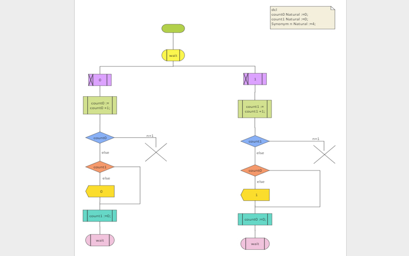
Click on the image to edit. Source: EdrawMax Online
2. Benefits of SDL Diagram
Compare the behaviour of the object-oriented application provided by various vendors to specify which one is better. After you create an SDL diagram to compare the behaviour of other applications, you can use it as a reference on how your application should behave. It will also help you understand if your required behaviour is similar to other applications.
Define consistent standards to explain better the communication between various components of your interactive system. Having an international standard for communication makes it simple for everyone. We use specification and requirement language to design and implement systems with parallel processing.
Understand the process flow in any SDL-based system with SDL diagrams. These diagrams help describe the description and specification of a system to illustrate its process flow using symbols and arrows. It makes it easy for anyone to understand the activities in the system.
Generate a desirable implementation of any system behaviour with an SDL diagram. You can use these diagrams to determine the required behaviour of your system. You can design and implement that behaviour with its graphical representation while developing interactive systems.
3. SDL Diagram Use Cases
Service Creation: You can use SDL diagrams in the service creation process. SDL diagrams provide the system's design with a complete definition of each component. It helps you capture the requirements of the user or customer. It also provides a good basis for service analysis to derive the system based on the captured requirements.
Validation: The system validation process determines whether the system conforms to the defined requirements in its development's design and analysis phases. You can use the SDL diagram to complete validation by comparing the required behaviour with the behaviour of the system you created.
Behaviour Specification: We use SDL diagrams to specify the behaviour of any real-time system with parallel processing. When developing a new system, its required behaviour depends on the user requirement and the system analysis. With SDL diagrams, we can compare the behaviour and structure of the developed system by documenting the provided behaviour.
4. How to do SDL Diagram?
Making an SDL diagram is similar to making a flowchart. As SDL diagrams illustrate the components of SDL-based systems, the key elements of the diagram is the system's behaviour. Make your diagram by keeping the required system behaviour in mind. Understanding the behaviour of any system is a complex task so before you move to a diagramming tool, specify its behaviour. Here are the steps to create an SDL diagram.
- STEP 1: Define the system and its required behaviour. When you create an SDL diagram, you need to identify the system's main components to visualize its activities and processes.
- STEP 2: The next step is to organize the processes, decisions, and data with their corresponding shapes in the flowchart. Graphically represent the agents of the SDL diagram in the second step.
- STEP 3: Use SDL diagram symbols to represent the communication between system components.
- STEP 4: Illustrate the process flow using arrows and connectors. Determine the sequence of each step from start to finish before depicting the process flow.
After you understand the SDL meaning, the next step is to get started with an SDL diagram maker. EdrawMax Online is the best SDL diagram maker because of its user-friendly interface and comprehensive collection of free templates. EdrawMax lets you export your diagram in all popular formats and also comes with a symbol library with all SDL symbols. Here are the steps to create an SDL diagram on EdrawMax.
- STEP 1: Log in to EdrawMax Online or create a new account.
- STEP 2: You can make your diagram using a template or open a blank canvas to draw it from scratch. Go to new, and click on the flowchart category. Select SDL diagrams and click on the "+" button to get a new canvas, or select a template to edit it right away.
- STEP 3: The next step is to customize your SDL diagram. Go to the symbols library and insert icons and symbols with a simple drag and drop. Add connecters to visualize the relationship between components.
- STEP 4: After your diagram is complete, the next step is to download it. EdrawMax Online supports various document formats, so you can export in any format you want. You can also share and print it.
5. SDL Diagram Examples
You can create an SDL diagram with a flowchart or a process flow diagram. There are many symbols and different layouts of an SDL diagram. Here are our free SDL diagram templates that you can use to create your diagram. Check out these examples to reference how to make an SDL diagram.
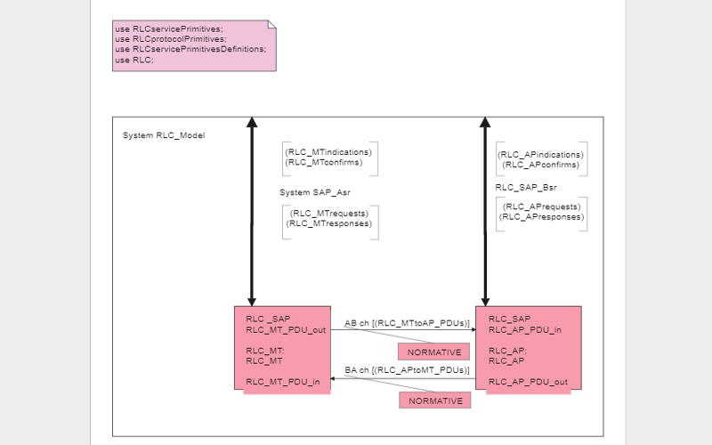
Example 1: SDL System Diagram
The SDL system diagram in this example illustrates the process design of an RLC model. It depicts the process flow and working of the RLC model. The system in this example consists of a resistor, capacitor, and inductor. You can use it to design electrical circuits and understand the relationship between each circuit element. The layout of the diagram is also clean and easy to understand.
Example 2: SDL Diagram Yes No
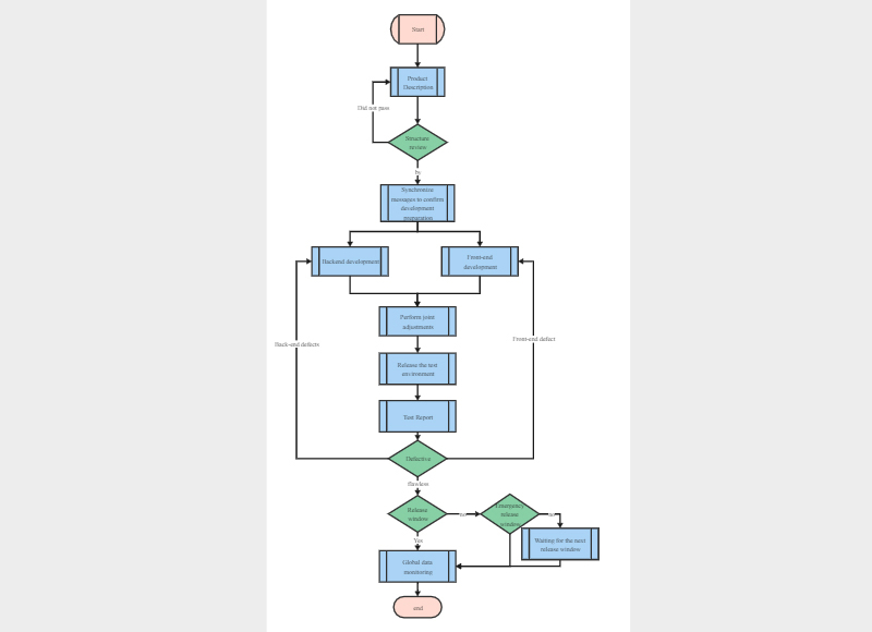
The SDL diagram yes no in this example graphically represents the system development process for both front-end and back-end activities. The diamond SDL symbol represents the process agents for a yes, or no decision making. This layout of the SDL diagram is also commonly known as the SDL flowchart. We use this layout to illustrate the decision making in the development process.
Example 3: Procedure SDL Diagram
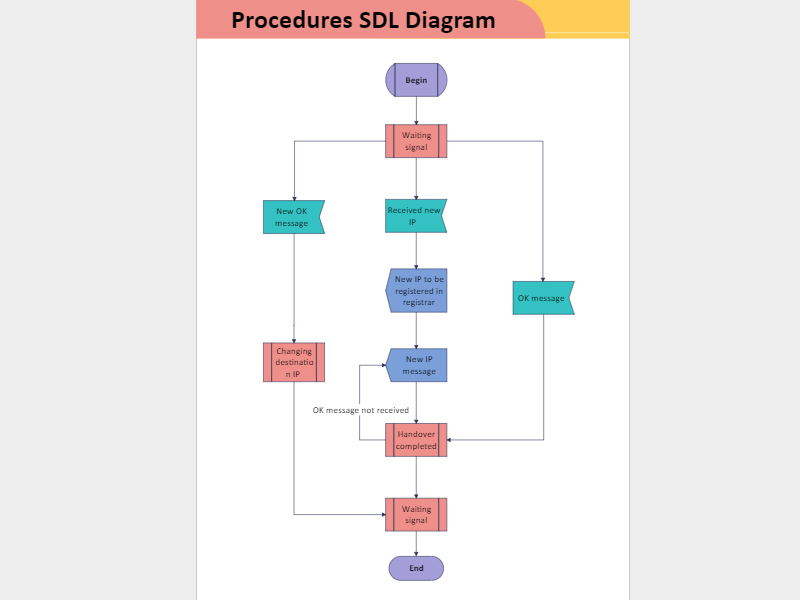
The procedure SDL diagram in this example depicts the process flow of an Ip specification system. It illustrates each step of the specification in an organized manner to showcase how the system registers new Ips and communicate with various components. It is a simple SDL flowchart with nested loops and clear output. You can use the template in this example to create an SDL diagram to depict all types of procedures.
6. FAQ About SDL Diagram
1.What is the SDL diagram in Visio?
The SDL diagram in Visio illustrates the specification and description language systems using ITU standard symbols. It helps you document communication networks and create a flowchart for object-oriented systems. Open Vision and navigate to the flowchart category. Click and drag shapes and symbols to represent processes in the flowchart. Use arrows to depict the process flow and add text.
2.What is an SDL in telecommunication?
Telecommunication software engineers mainly use the specification and description language to design and develop complex real-time, distributed, object-oriented systems. It is a modeling language to specify the behaviour and requirements of interactive systems. You can also use it to define the internal structure after defining its internal schema.
3.What is software description language?
We use the software description language to create the architecture of the software. Software developers use this language to describe a notation with exact semantics and syntax. It takes the mind of developers away from writing codes and focusing on the software architecture to understand its elements. It makes it easier to understand the structure of any software, which helps in the designing process.
7. Key Takeaways
The SDL diagram is a visual representation of the components of the specification and description language used to model object-oriented system diagrams. Software engineers use it to design state communication machines and develop complex real-time software. You can easily create an SDL diagram with EdrawMax Online. It gives you free SDL diagram templates and many unique customization tools. It also supports various document formats. Save time and effort by making your diagram on EdrawMax. You can easily create a spider map on EdrawMax Online. It gives you free professional templates and a symbol library to make your diagram. It also comes with unique customization tools and supports various document formats. Find more SDL diagram examples.
