What is Block Diagram – Everything You Need to Know
Create a Block Diagram Online Free Free Download Free Download Free Download Free Download1. What is a Block Diagram?
A block diagram is a drawing illustration of a system whose major parts or components are represented by blocks. These blocks are joined by lines to display the relationship between subsequent blocks.
We use block diagrams to visualize the functional view of a system. It uses blocks connected with lines to represent components of a system. With a block diagram, you can easily illustrate the essential parts of a software design or engineering system and depict the data flow in a process flow chart. You can learn everything about a block diagram, including its uses and types. Check out some of its most used examples and learn how to create your block diagram.
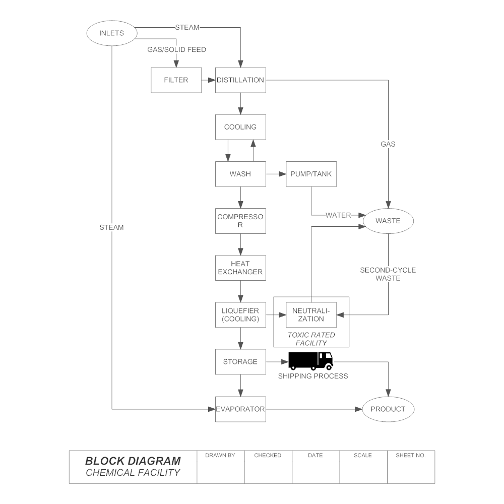
Image Source: smartdraw.com
2. Block Diagram Symbols and Basic Components
| Symbol Name | Function |
| Blocks | Rectangular blocks in a block diagram represent operations in the system. It is usually connected with two lines from left and right, and one of the lines carries the input while the other gives the output. |
| Lines | Lines in a bock diagram depicts the system process flow and the interrelationship of components and operations. You can use a straight line to connect blocks and arrowhead to represent the process flow. |
| Summation | A cross inside a circle is the summation symbol in a block diagram. It is commonly used in charts from engineering systems, and it sums two inputs together and gives a single output. |
| Differentiator | We use “S” in a small block as the differentiator symbol in a block diagram, and it computes the rate of input and output in the system. You can also use it as a rate take symbol by replacing the "S" with "rate". |
| Integrator | We use the mathematical symbol for integration to illustrate an integrator in a block diagram. You can use various shapes with the integration symbol to customize your integrator. |
To sufficiently and efficiently represent meaningful processes and display how particular building blocks are interconnected, you need the internal block diagram to study how the blocks’ properties and components get integrated.
In the internal block diagrams, the structure and flows within blocks are described using the OMG Systems Modelling Language (SysML). They provide us with a simplified explanation of how block components are related to one another, what type of data, details, signals, or material flow between the elements and in what direction they flow.
These block components are mainly five and include:
-
Block: it represents the logical and physical components of the system.
-
Part: it comprises all aspects modeled using aggregation and association.
-
Reference: it has all the parts which were developed using aggregation and association.
-
Standard Port: this is the point of interaction between a system block and the corresponding environment.
-
Flow Port: this is the point of interaction where a block can emerge from or to.
It is essential to understand the terms used in describing the relationships within Block Diagrams. These are:
-
Association: it explains the communication amongst the blocks.
-
Aggregation: this term describes how a unit gets made of parts.
-
Composition: it is a proper form of aggregation in which the existence of an object which is part of a unit relies on the presence of the group.
-
Generalization: is a leading relationship between blocks in which a designated block contains all the properties of the entire block diagram.
3. Why are Block Diagrams Important?
What significant role do Block Diagrams play? Well, a Block Diagram is a fundamental way that hardware and software developers utilize to describe these systems while illustrating their workflows and processes. Electricians, on another hand, need them to represent systems and their shifting, for example, the mechatronic systems in the trucking industry.
More often than not, block diagrams are of great assistance when a clear picture of information or control flows is required, besides when a project has a myriad of processes. They make it easier to represent complicated algorithms or flows of details or communication among precise components, for instance, in a mass production facility. Graphically represented project processes are less strenuous to understand than when they are in text form.
When you walk into a room with a block diagram, you will be able to easily decipher the system’s details, interface, and such as structure aspects. It is all thanks to how the blocks are connected intellectually to one another by lines. Blocks are convenient when designing new processes and upgrading those that already exist.
4. Uses of Block Diagrams
Being simple and easy to understand, Block Diagrams are used in most industries to illustrate functional processes in respective fields. Next, we will look at three most areas that make use of block diagrams.
4.1. Block Diagrams for Software Design
A block diagram makes a very efficient representation of the overall running of a computer system. It displays the necessary processes needed to get the desired output from a computer from the input you feed into at the start.
In the diagram below, the control unit (CU) and the arithmetic & logic unit (ALU) make up the Central Processing Unit (CPU) in a computer. It is the brain cum the heart of a computer system. Intermediate data and results are contained in the memory unit, awaiting processing. And the disk storage unit houses data and instructions input into a computer system by an input device.
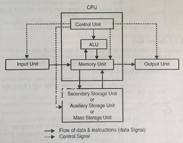
Image Source: pdffiles.in
4.2. Block Diagrams for Electrical Engineering
The diagram below is an illustration of an instrumentation channel designed to measure neutron flux, display measured flux, and generate output signals for use by other systems. Every single block marks a stage in the development of a signal used to display on the meter at the lower end. Or to send to systems beyond the boundaries of the diagrams. The blocks are of different sizes and represent either multiple functions, straightforward stage, or one bistable circuit in a more prominent component.
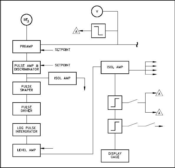
Image Source: myodesie.com
4.3. Block Diagrams for Process Control
The third block diagram example is of a feedback control system. It is used to display the essential elements of the system through simple and clear interconnectedness. While studying one, it is very crucial to keep in mind that a block diagram only represents flow paths of control signals. Do not be misled to thinking that it also shows how energy gets transferred throughout the system or process.
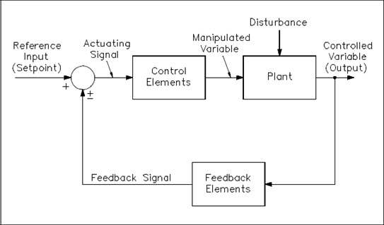
Image Source: akkordeon-frankfurt.de
5. Block Diagram Examples
Below are three frequently used block diagram examples, you can find more block diagram templates in Template Community.
Functional Block Diagram
This functional block diagram example illustrates the working process of a coffee blender. It explains the active view of each component and activity in the system from when the user starts the process and gets the final product. There are many blocks linked with each other depicting the process flow. The user gives the input, and the system mixes the user's components. Before that, it heats the water and makes preparations to blend coffee. It also takes care of the overflow safety and stops heating when the coffee is ready.
Source:EdrawMax Online
Electrical Block Diagram
This electrical block diagram example visually represents a wind-diesel hybrid renewal energy system. The reader can quickly get the general idea of the functional view and the process flow from this block diagram. You can see that the icon at the start represent wind energy coming from windmills. The energy changes into electrical energy and moves to the controller. It measures the demand, and if the energy is not enough, the system uses diesel to complete the requirement. The black line that connects the block is the power line, and the red line depicts the data flow in the system.
Source:EdrawMax Online
System Block Diagram
This system block diagram example illustrates the functional view of the door-open system. It depicts the components and process flow of automatic doors installed in commercial buildings and malls. The user first enters security information using the keyboard and the screen, and the system checks it and moves the process with a microcontroller. If the information is not correct, the system gives a buzzer sound. After the recognition, the servo motor opens the door automatically. You can see that it is easy to understand the working process and components of an open door system with a system block diagram.
Source:EdrawMax Online
6. How to Create a Block Diagram
Now, let us see how we can use this concept to draw a block diagram with EdrawMax Online.
Step 1: After registration and verification, log in to the site and choose Basic Diagram under Available Templates. Select either 2D block or 3D block as desired and carry on.
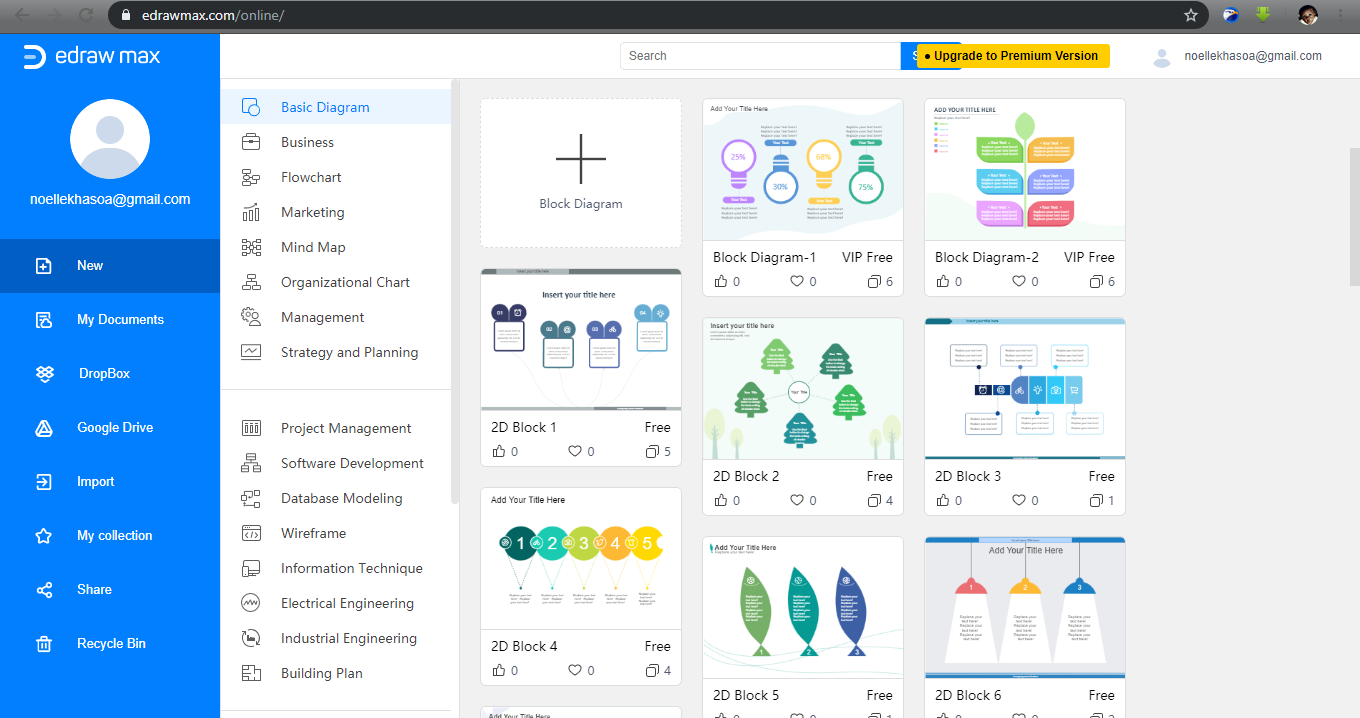
Step 2: Find the Library pane on the left side of the interface, then tap and hold on a block shape. Carefully drag and drop it onto the canvas displayed on the right side of the screen. To adjust the shape’s size, use the green selection handles.
Step 3: Now, if you need to write inside the block, double click on it. Add another block shape next to the existing one through drag and drop, as you did in step 2 above.
Step 4: To choose a connecting design, tap on the Connector icon at the top of the screen to display the drop-down menu. Then tap on the first block shape and draw a line from the edge of this shape to the following form. The connections end turns red indicating, the successful joining of blocks.
Do this until the block diagram gets entirely joined.
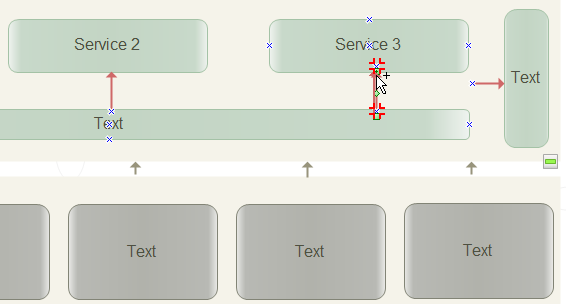
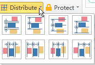
Step 5: polish up the block diagram by aligning and distributing the shapes and using preferred colors or patterns to identify specific block parts. You have to label the blocks accordingly to ensure you have an ordered and distinct block diagram.
Step 6: Lastly, choose whether to save or export the finished block diagram
7. Tips for Making a Block Diagram
Whether you are a beginner or a pro, we have some tips for you to help you make the perfect block diagram.
- Study and understand the system firsthand. Find out the method that you will use to make a block diagram. Figure out its components, inputs, and outputs.
- Design and mark the diagram. Use symbols intellectually to represent specific parts of the system. Always connect the blocks using arrows to show the flow of the process. Naming the blocks is very crucial for easy identification.
- Show the Input and Output. Ensure you exactly mark the input, which indicates the start, and the output, that indicates the end of a process in a block diagram.
- Accuracy verification. Before putting the diagram out there for use, confirm with the concerned and involved team about its accuracy. You should all be on the same page regarding the block diagram’s correctness.
8. Block Diagram FAQ
What is a Functional Block Diagram?
We use functional block diagrams in software and system engineering. It illustrates the functional view and relationships between the components of a system using blocks and lines. It is commonly used to depict a programmable logic controller's logic flow and system design. It makes it easy to understand the interconnections of a system. Blocks of various sizes typically represent each process and element.
What is Flow Block Diagram?
A flow block diagram is different from a general block diagram. It illustrates the functional flow of a system in a step-by-step process flow by adding elements and activities in a time-sequenced manner. This diagram is commonly used to represent complex systems. With a flow block diagram, the reader can easily understand the internal structure. The process flow usually moves from left to right.
What is Block diagram Maker?
You need a block diagram maker to create a perfect block diagram. From a diagram maker such as EdrawMax Online, you can get many professional templates and customization tools to make your diagram. It also gives you a comprehensive library of symbols and icons to use and create a chart from scratch.


