What is a Data Flow Diagram (DFD)?
DFD, which stands for Data Flow Diagram, provides a visual representation for the flow of data across a system. Ideally, there are three major components in a DFD – entity, database, and process. An input or output unit can be defined as an entity and processes establish a relationship between entities/database units. Ideally, a data flow diagram acts as a flowchart for business processes and information systems. Since it has such a wide range of application, it is commonly used in numerous sectors these days. Let’s get to know what is a Data Flow Diagram and how to create it in this informative guide.
1. What is a Data Flow Diagram?
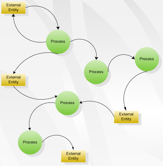
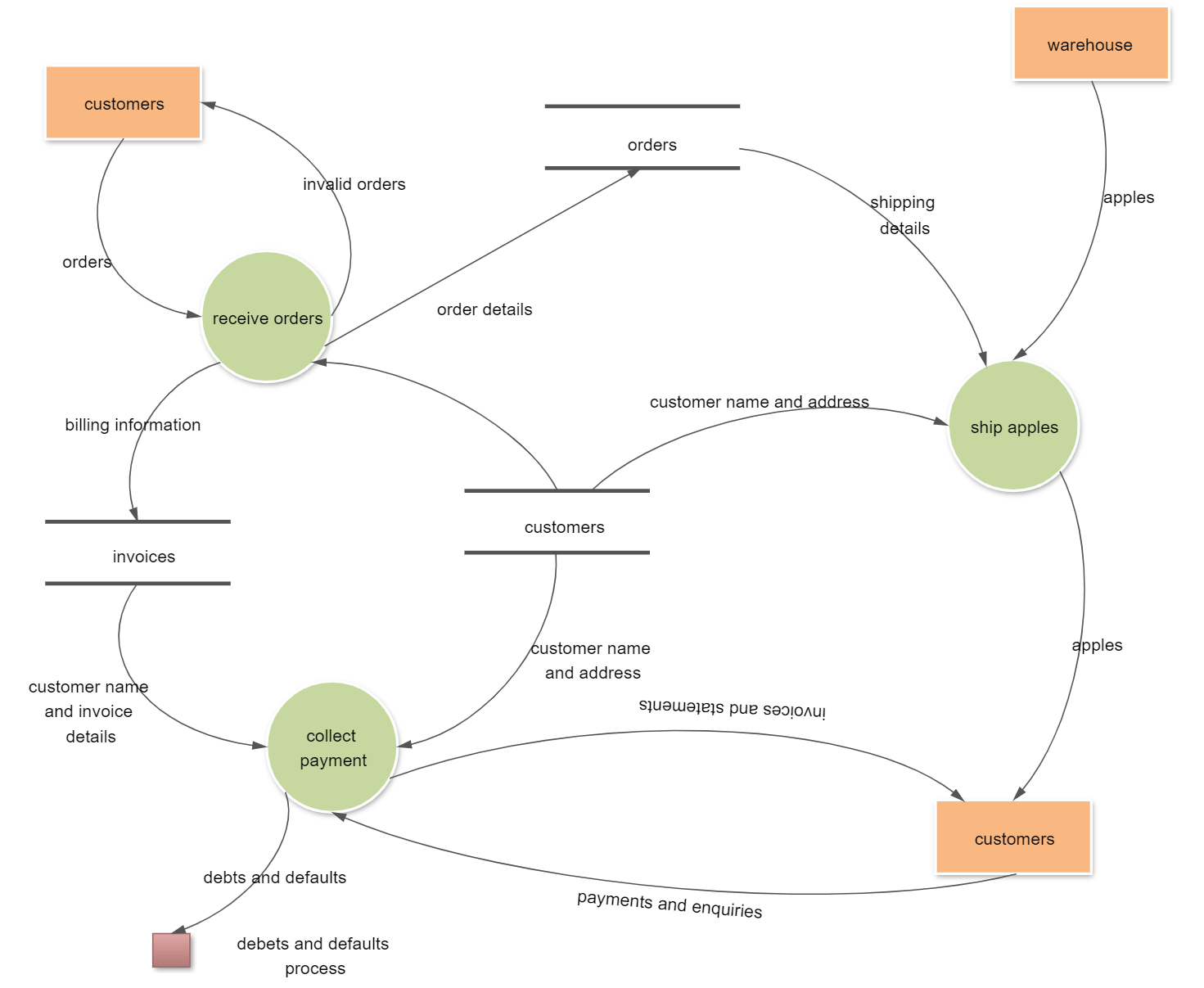
As the name suggests, a Data Flow Diagram represents how data is passed through a system. To do this, it provides information about the input, output, and the processes related to the system. In simple words, it depicts the flow between different entities in a system and how data is processed. Mostly, it looks like a flowchart and helps us work on database management and system analysis.
Click on the image to edit. Source: EdrawMax Online
2. History of Data Flow Diagram
Before we get to know what a Data Flow Diagram is, let us quickly discuss its history. The concept was originally derived from graph theory and gained popularity in the 1970s when Ed Yourdon and Larry Constantine released their Structured Design book. Though, it was David Martin and Gerald Estrin that coined these graphs as “data flow models” with their academic research.
Gradually, the concept was linked with Object-oriented Analysis and Design as it makes it easier for developers to visualize their system’s data flow. As of now, it is considered as a part of structured analysis modeling and is closely related to UML’s activity diagram.
3. Applications of Data Flow Diagrams
Since DFDs are so easy to make and have a universal appeal, they are used in numerous ways. Following are some of the major applications of Data Flow Diagrams.
Database designing
With the help of a complete Data Flow Diagram, we can come up with the overall design of the database. Ideally, a DFD is drawn before database creation as it provides the conceptual and physical structure of the database that can later be used.
System analysis
Apart from designing the database, DFD can help us understand how the overall system works. By examining the flow of data from one entity to another, we can further analyze the working of the system and its input/output entities.
Decision making
Engineers need to make tons of decisions during the creation, implementation, and deployment stages of the database. A DFD can help us make better decisions by providing an overall visual representation of the system.
Error detection
In case if there is an issue with your system, then you can scan the DFD. This will help you detect any error and even resolve it in the long run.
Other applications
There are numerous other organizational and management applications of a DFD. This is why they are so extensively used in business processing and management sectors.
4. Data Flow Diagram Symbols
One of the best things about Data Flow Diagrams is that they are extremely easy to make. To start with, you need to consider the following symbols to represent entities and the flow of data.
Process: This represents any task that is performed by the system on the input data. It results in a processed output of data. A process can be related to the modification, storing, deletion, creation, or any other operation on data. It is represented by a circle or a round-edged rectangle.
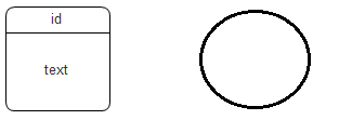
Database: This is where data is stored in a system. It can also be the input or output of a process as well. It is represented by a rectangle, which can sometimes have a small section for its ID.

Entities: They are either the source or the termination of the DFD. Ideally, they represent an external source from where data is taken or processed in the end. Entities are represented by a closed square/rectangle.

Data Flow: Lastly, we use directional arrows to represent the flow of data from one entity/database to another. The line would have a directional arrow in the end to depict the source and the destination units.

Apart from the Data Flow Diagram symbols, also consider the following common rules in mind:
- A DFD has to be complete and includes all the vital components of the system.
- It should be consistent in nature. That is, if you are working on one level, it should only be nested with another level.
- There should be no direct link between one entity/database to another entity/database. A process should be present in the middle of entity-database, database-database, and database-entity connection.
- Each component in the system should have at least one data flow linked to it.
- There should be one specific source and an output unit in a DFD.
5. Data Flow Diagram Levels
Data Flow Diagrams are composed of levels and layers, from the basic to the higher level. The level of the diagram depends upon the scope of the process. As the level increases, the complexity of the diagram increases. The high-level Data Flow Diagrams are categorized into low levels with more detailed process information.
Level 0 DFDs
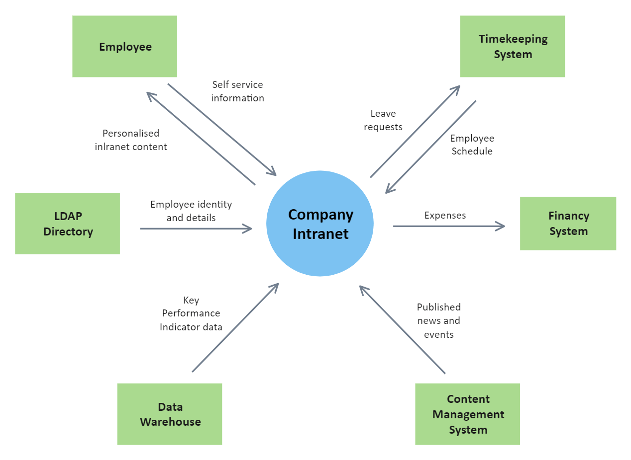
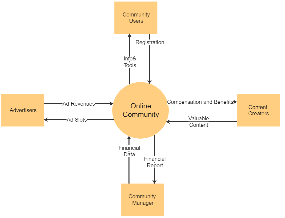
The Level 0 data flow diagram gives a general overview of the process. They are also called context diagrams. The level 0 DFDs depict the single process node and its links with external entities. It is understood by all the stakeholders participating in the activity.

Level 1 DFDs
The Level 1 data flow diagrams are the more detailed breakout of parts of the Level 0 DFDs. In a level 1 DFD, the single process node is broken down into sub-processes with additional data flows and data stores to connect them.
Level 2 DFDs
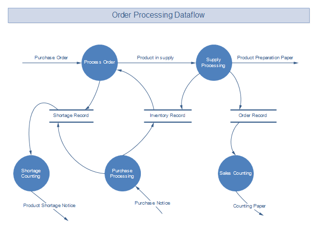
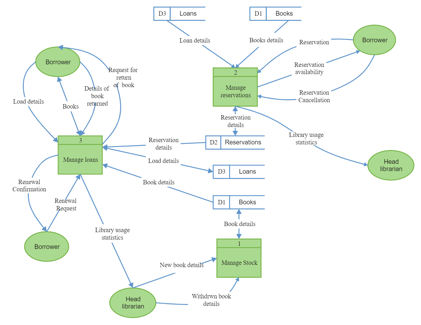
The Level 2 data Flow diagrams go into deeper sub-processes to better illustrate a process and its stages. More symbols, shapes, and text are required to detail the process depicting the system's functioning.
6. DFD Examples and Use Cases
Example 1: Software Engineering
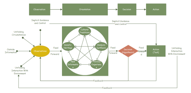
This diagram is the data flow diagram of the Implementation of the Software; the engineers in the software house first understand the needs and requirements, then picture the whole scenario in the planning part, then research is conducted to design the software. After the research development is done, the design is monitored, and its performance is evaluated; if it does not meet the requirements, planning is being done again. The software is then coded, and performance evaluation is conducted for any required changes, after which the process ends.
Example 2: IT
Here is another example of a cross-functional flowchart of multiple departments of an organization, but let's consider the finance department now; the Finance department comprises seven sub-processes or jobs. As depicted in the flowchart, the Finance department is responsible for cost control, Treasury information and management, settlements, and payments, management of duties and taxes, asset management, and the most important one, Accounting.
Example 3: E-commerce
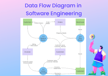
This diagram is the data flow diagram of order processing in an E-commerce store. When the customer places the order, the payment comes, and if the credit card information is accurate, the system tracks the user's address. Then the admin puts the user's information and order into the computer prints invoice and shipment label, after which the package is ready to be shipped.
Example 4: Product Management and Design
This diagram is the data flow diagram of the product designing and management. The first step includes analyzing the current market in which the company is currently operating; then, new markets are also being investigated. New ideas are brainstormed on penetrating the new market, and production cost and profitability are calculated.
If the proposal gets approval, test production in the market is done. If there is a healthy response from the market, then large-scale production opts, and in case of poor response, production is stopped immediately. Once the large-scale production starts, then come to the advertising and marketing of that product to generate sales, then cost evaluation of the advertising is conducted. If it gets approved, advertising campaigns start, after which finally the product is introduced into the market.
7. Logical DFD vs. Physical DFD
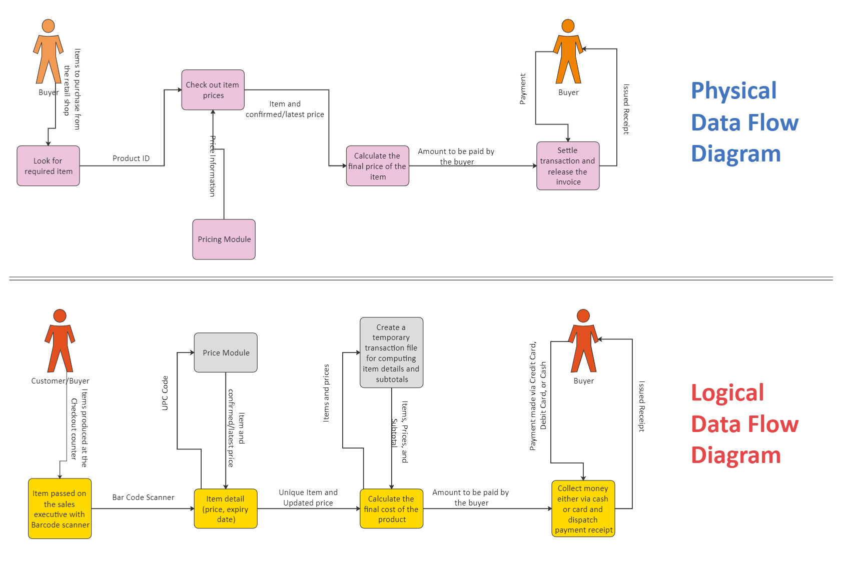
A logical diagram provides an overview of the business activities in a system. It doesn’t focus on how the data is stored rather it lets us know how it is implemented. It provides business controls and the flow of data from a user perspective.
On the other hand, a physical layer provides a more low-level representation of how the data is stored. It consists of databases and physical entities that are needed in a system. There are all kinds of manual processes and core data-driven decisions that we can make out at a physical level.
Click on the image to edit. Source: EdrawMax Online
8. Advantages and Limitations of DFDs
Now when you know what a Data Flow Diagram is, let’s dive into its details. If you want to make DFDs regularly, then you should be aware of their advantages and limitations as well.
Advantages of DFD
As per the requirements of the process to be documented, its diagram or flowchart should be chosen. With the help of all stakeholders participating in the activity, a flowchart as the base should be selected to start designing and documenting.
- Data flow diagrams are pretty simple and considered easy to make. No thorough training is needed to work on them.
- They are extremely diverse and can be used to depict the flow of data in almost every possible system.
- Apart from databases, DFD can also be used to depict input and output entities. This helps us draw comparisons with the real-world entities.
- There are all kinds of levels and structures in DFD. This can help us get an extensive representation of the system.
- It provides a precise and clear representation of the data flow, without involving any unwanted entities.
- It lets us understand the logic and concept behind the system and helps with its organizational management.
Limitations of DFD
- It does not provide a complete picture of the system and leaves some vital physical entities.
- Sometimes, a DFD can be confusing and programmers might not differentiate between its levels.
- At times, it can be tough to conceptualize an object-oriented structure in a hierarchical format.
9. How to Create a Data Flow Diagram with EdrawMax?
To create all sorts of Data Flow Diagrams, you can consider following this stepwise process.
Step 1: Pick the DFD level
Firstly, you need to identify how you are going to represent the system. Just pick between the physical or logical layers and the level at which you will represent the process.
Step 2: Identify key entities and processes
A Data Flow Diagram is all about key entities and the processes connecting them. Therefore, you need to identify the input and output sources of the system and how they would be processed.
Step 3: Use EdrawMax to make a DFD
Once you have everything ready, you can take the assistance of a dedicated tool like EdrawMax. It has readily available templates for DFD that you can choose to save your time and efforts.
A canvas would be loaded in the center while you can view different vectors and options on each side. Simply drag a vector from the sidebar and drop it to your canvas. There are readily available vectors for entities, processes, data flows, etc.
Without any prior designing experience, you can easily customize them. Double click the vector to add your own text, draw connections between different entities, and change the overall appearance of the diagram. In the end, you can simply export it in the format of your choice.
10. Online Data Flow Diagram Maker
Who knew it would be so easy to work on Data Flow Diagrams, right? With the help of a professional tool like EdrawMax, you can come up with lots of useful DFDs in no time. It has a friendly interface and has included several templates to pick from. Also, with its numerous editing features, you can draft a customized DFD on any topic. There is no prior designing experience needed to work on EdrawMax. The best part is that it offers a free trial version as well. So what are you waiting for? Go ahead and try this remarkable tool for free and be the judge of it yourself!
