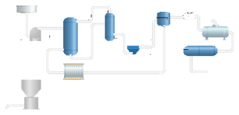
The image presents a schematic representation of an industrial process system, presumably for fluid handling based on the visible components and connections. The diagram features a series of interconnected vessels, pumps, and heat exchangers, each connected by pipelines. Starting from the left, there is a storage tank connected to a pump, which appears to feed into a series of vertical and horizontal vessels, possibly reactors or separators. Below this assembly is a heat exchanger, suggesting a temperature control step in the process. Toward the right, the system includes a cylindrical unit with a label that is not legible in the image, which may be a filter or a dryer, leading to a final storage or collection tank. The pipes include direction arrows, indicating the flow of material through the system. The layout is clean and systematic, with a clear delineation of process flow, and the components are depicted with a high level of detail that suggests specific functions within the overall system.