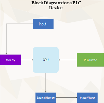
This EdrawMax template provides a clear and concise block diagram illustrating the fundamental components of a Programmable Logic Controller (PLC) Device. Central to the diagram is the 'CPU' (Central Processing Unit), which is connected to 'Input' for receiving signals, 'Memory' for storing data and instructions, 'PLC Device' for executing control tasks, 'External Memory' for additional storage, and an 'Image Viewer' for interface display. This diagram serves as an invaluable tool for electrical engineers, technicians, and students specializing in automation and control systems, offering a snapshot of PLC's internal workings and connectivity.