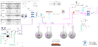
This template is a detailed process flow diagram for the LNG to FSRU operation. It features multiple colored lines representing different flow paths, such as main feed lines and vapor lines. The diagram includes several key equipment components like LP (Low - Pressure) and HP (High - Pressure) modules, vaporizers, and compressors, with their specifications listed in a table on the left. Symbols and legends are used to clarify the different elements and connections. Four large circular tanks are shown in the center, indicating storage areas. The bottom part of the diagram depicts the engine room and other related systems. There is also a ship icon representing the LNG carrier. This diagram is crucial for understanding the operational flow and equipment in an LNG to FSRU setup.