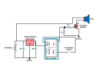
This circuit diagram illustrates a simple horn control system using an Arduino Uno microcontroller. A push button switch triggers an input signal to the microcontroller, which then controls a MOSFET (M1) to activate the horn. Components like resistors R1 and R2, capacitors C1 and C2, and a voltage regulator ensure proper power supply and signal conditioning for the microcontroller and MOSFET.