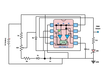
This circuit diagram illustrates a Pulse Width Modulation (PWM) setup, demonstrating how to control the duty cycle of a signal for various applications. It outlines the components and connections required to generate and adjust PWM signals. Ideal for motor speed control and signal modulation.