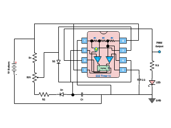
The Pulse Width Modulation (PWM) Circuit Diagram is an essential electrical schematic used to control power delivery to devices by varying the width of the pulse in a signal. This technique is commonly applied in motor control, LED dimming, and signal modulation. The diagram typically features a microcontroller, resistors, and transistors, illustrating an efficient method for adjusting output power.