How to Draw P&ID in AutoCAD
1. Introduction
P&ID diagram is an acronym for Piping and instrument diagram; it is also known as process and instrumentation diagram. Piping and instrumentation diagram (P&ID) is a detailed diagram used in the process industry for piping and equipment in the process flow, and it also includes the instrumentation and control devices.

2. How to Create a P&ID Diagram in Autocad?
P&ID stands for Process and Instrumentation Diagram to show the piping and other related items for process flow. Autocad P&ID represents a detailed graphical representation of the complex process system, including the piping, valves, instrumentation, equipment, and other process components in the system. In Autocad, p&id diagrams can be created using the variety of symbols available. It is an engineering diagram, and usually, process engineers are responsible for this diagram.
1. Uses of P&ID
- P&id diagrams are used in the planning & construction phases of different plants in the industry. This diagram provides a map for design and acts as a blueprint later for maintenance and modification of the process.
- It assists in the operation of the plant.
- It also supports mechanical technicians & safety personnel for audits and safety reviews.
- Autocad p&id diagrams are properly laid out and can be used as a controlled document at various stages of the project
2. Steps of Creating a P&ID Diagram in AutoCAD
AutoCAD P&ID software provides a framework for creating schematic piping and instrumentation diagrams that can later be modified and managed in the same program. AutoCAD Plant 3D can also add 3D models, including piping, equipment, support structures, generation of isometric, and orthographic drawings.
Drawing AutoCAD p&id diagrams is a straightforward process with a few steps.
- Before starting drawing AutoCAD p&id diagrams, you must decide the blocks that you will be using. So, open the new document and draw the blocks of the equipment or instruments required in the design.
- Connect the blocks with a line according to the sequence.
- It is important to name each line segment for easy referencing. The best practice is to use the size, serial number, and construction material while naming the line segment.
- Also, name each piece of equipment and instrument that is sensible and follows a convention.
- Electrical lines, pneumatic lines, and hydraulic lines should be represented by different types of broken lines and be named.
- Click the [Schematic] tab > [Insert Components] panel > [Insert P&ID Components].
- To add equipment, in the [Insert Components] > [Piping and Instrumentation Symbols] dialog box, click equipment.
- Repeat steps of insertion as required.
How to Create a P&ID diagram in EdrawMax Online?
EdrawMax Online is a drawing program that is available online and as a software download. It is a comprehensive program with well-equipped symbol and template libraries for creating p&id diagrams among 280+ other drawing types. Here is the simple method to create P&ID diagrams in EdrawMax Online.
If you want to create a document from scratch, then;
1. Sign in to your account and go to https://www.edrawmax.com/online/en/. Navigate to [New] > [Industrial Process] > [Process P&ID]. When you click the diagram name, you see a blank canvas with symbols on the left-hand side. Use drag-and-drop actions to create your required diagram.
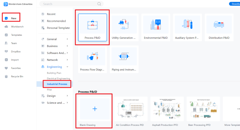
To make things even easier, you may select a suitable template from the library and customize it according to your requirements.
2. Go to template gallery and search for p&id. Select the suitable template, click the "Use Immediately" button at the top and open it to customize and modify.

Use symbols, icons, and objects connected with lines to design your required diagram.
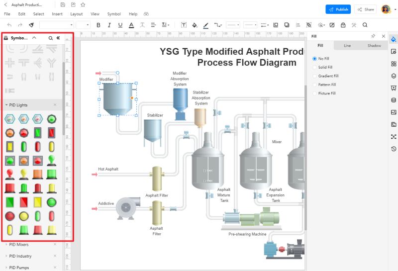
Save your document. You can download it in the .eddx format of EdrawMax. Also, this program allows you to export your document in several famous formats like PDF, JPEG, Visio, Powerpoint, and others.
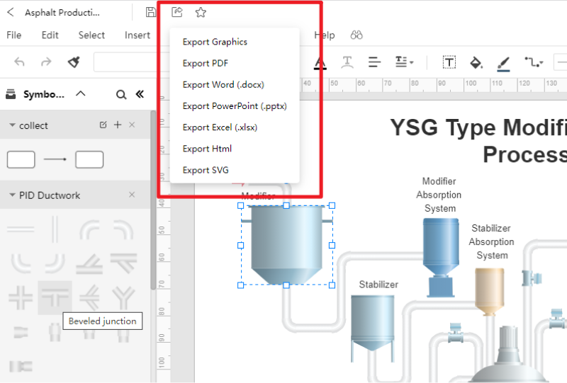
4. P&ID Diagram Templates
P&id diagram drawing can be a complex process; however, with proper tools and skills, you can make the process simpler. Following are some examples of the p&id diagram for further reference.
Example 1: Engineering P&ID Diagram
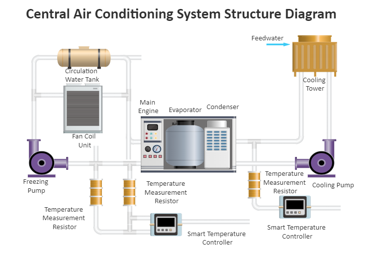 Source: EdrawMax Online
This P&ID diagram is about a central air conditioning system complete with equipment, connections, and process description. Such diagrams are helpful in the design and installation process and support the system throughout its lifespan. Since most of the equipment and installation details are concealed, this diagram helps identify the faults and bugs for quick repair and maintenance.
Example 2: The Freezer Machine P&ID
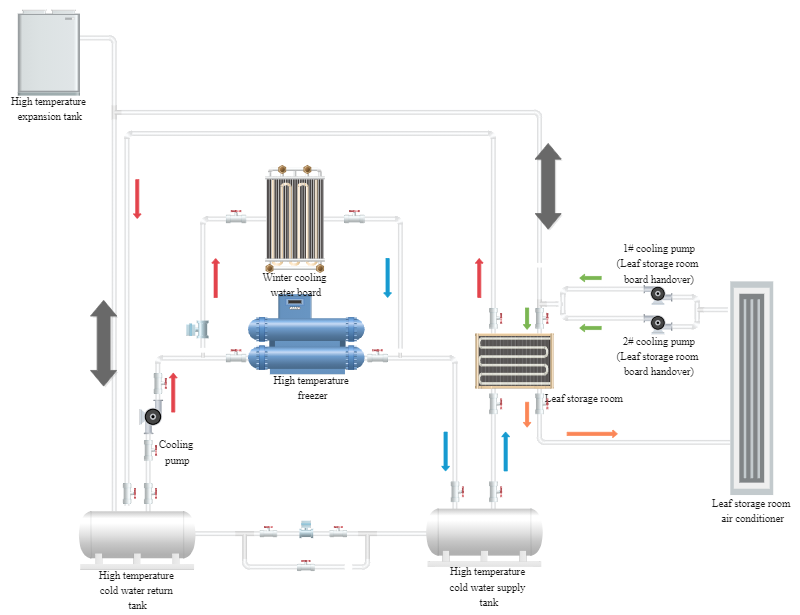 Source: EdrawMax Online
The schematic diagram of the refrigerator includes all the equipment, including the expansion water tank, plate heat exchanger, return cylinder, etc., and other supporting equipment and their connection methods.
Example 3: Wastewater Treatment Plant PID
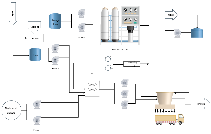 Source: EdrawMax Online
This is a wastewater treatment plant P&ID drawing of a processing plan that includes the piping and process equipment. It shows the design with the piping and associated parts of a physical process flow. It starts from the water inlets, covers the whole process till the filtered water leaves the plant. The distinguishing feature of EdrawMax Online is the representation of the p&id diagram.
5. Online P&ID Diagram Maker
Online P&id diagram makers are very convenient softwares and you do not even have to download them to work. EdrawMax Online is a program that allows you to create AutoCAD P&id diagrams conveniently with drag and drop functionality. It is a wide variety of symbols for different types of diagrams. The template library available at template gallery is fully equipped with templates for more than 280+ types of diagrams that are free to customize and use.
Using EdrawMax Online, you can come up with professional-looking ecomaps. You can either make one from scratch or use a template to save time and effort. With the simple drag-and-drop method and the customization tools, EdrawMax Online is a great platform for creating ecomaps.
Wondershare EdrawMax
EdrawMax is the easiest diagramming tool that serves all your purposes. Try Free Online now!


6. Key Takeaways
- The P & ID diagram visually represents all piping and physical sequences of branches, reducers, valves, equipment, instrumentation, and control interlocks.
- It is useful in the design of plants and maintenance and repairs also.
- Autocad P&id diagrams are functional; however, diagrams made with EdrawMax Online are visually more descriptive because they show the equipment and connection in a more realistic form. EdrawMax Online is free, very easy to use and even provides pre-made templates for different diagrams.


