Use Case Diagram Explained
Create a Use Case Diagram Online Free Free Download Free Download Free Download Free Download1. What Is A Use Case Diagram in UML?
In Unified Modelling Language (UML), use case diagrams are used to show the interactions between actors and a system. The system can be a website or another similar entity being developed. An actor is a person or entity that interacts with the system - normally, this is a user.
In essence, use case diagrams depict the system, who is using it, how they are using it, or what they are doing. On a macro scale, the information you can glean from use case diagrams allow you to set the scope of your system or application and what goals it can help the actors achieve.
2. Why Use A Use Case Diagram?
Use case diagrams aren’t the most detailed diagram. As such, they are usually used at a high-level of design. For a more comprehensive view of the system, it should be used in conjunction with other diagrams.
Use case diagrams are typically used in the following scenarios:
- Depicting the scope and goal of the interactions between the actor and the system.
- Modeling the interactions between actors and the system, as well as the general flow of events.
- Identifying internal or external factors that might impact the outcome of interaction and, by extension, the system itself.
- While use case diagrams are typically used in software modeling, they have also been adapted for business uses to depict value results to the actor when he or she interacts with the system.
- Use case diagrams CANNOT be used to model the order in which events occur.
3. Use Case Diagram Symbols
The most commonly used symbols for use case diagrams are as follows:
|
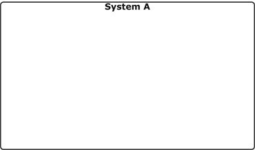
System
The rectangular boundary is the system. Use cases fall inside it, and actors will be placed outside it. |
|
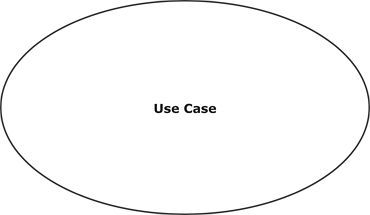
Use Case
An oval shape represents a use case. Use cases represent the functionality of the system, as well as the end-goal of the actor. Use cases should be placed inside the system. |
|
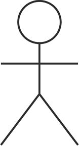
Actor
When an actor interacts with the system, it triggers a use case. Actors should be placed outside the system. |

|
Relationships
Arrows are used to indicate a relationship between an actor and a use case, or between two use cases. An extension indicates that one use case may include the behaviour of another use case. An inclusion represents one use case using the functionality of another use case. |
4. How to Draw A Use Case Diagram Online?
EdrawMax’s intuitive software allows you to create your own use case diagrams. Whether it’s a basic or complex one, follow this outline to create one that fits your needs.
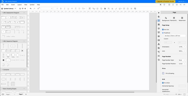
- Step 1: In your browser, visit https://www.edrawmax.com/online/ to access the online version, or download the desktop version at https://www.edrawsoft.com/download-edrawmax.html
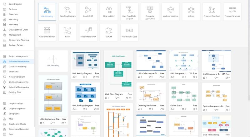
- Step 2: In the white sidebar, click on Software Development. Then, click on the UML Modelling box that appears near the top of the screen.
- Step 3: Choose a template, or click on the UML Modelling box with the “ + ” to open a new document.
- Step 4: The symbol library can be found to the left of the screen. Scroll down further to find more UML-related symbols.
- Step 5: Simply drag the components you need from the symbol library onto the blank document to start creating. Each element can be moved, resized, or customized to fit your needs.

5. Use Case Diagram Examples and Tips
Here are three examples of UML use case diagram created on Edraw Max.
Diagram 1: Online shopping system use case diagram
This is an example of how an online shopping system might be used in an use case diagram.
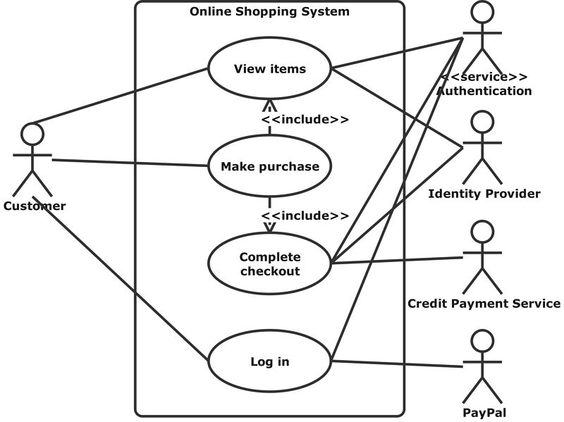
Diagram 2: Student Management System Use Case Diagram
This is an example of how an student management system might be used in an use case diagram.

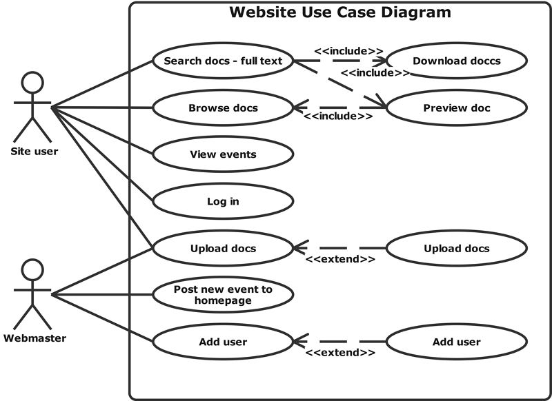
Diagram 3: Website Use Case Diagram
This is an example of how an web system might be used in an use case diagram.
EdrawMax’s Top Tips: How to make the most of Use Case Diagrams?
- Keep your use case diagrams as simple as possible - they are high-level diagrams and shouldn’t be too granular.
- All interactions with the use case should be represented in the diagram.
- Sequence diagrams can be used in conjunction with the use case diagrams for a more detailed view of the user’s goal.
6. Summary
Sometimes the most straightforward diagrams can be the most effective. That is what use case diagrams can offer - a simple representation of interactions between actors and a system. For situations where you need a high-level overview of a system, look no further than use case diagrams. Check EdrawMax for the best diagram tools out there!


