What is A Network Diagram
Create a Network Diagram Online Free Free Download Free Download Free Download Free DownloadWhat is a network diagram?

Image Source: pexels.com
In simple terms, a network diagram is a presentation of workflow in a graphical manner consisting of boxes or arrows. It helps the project team members or other readers to properly understand the concept of the project, including schedule, sequence and ending. They are mainly used in computer telecommunication to represent the network’s graphical chart while compiling the detailed documentation. This unique cluster diagram is made up of interconnected systems or groups, along with the dependency of each method on others.
As a member of the project team, you should know the importance and how to prepare a network diagram. Well, if you are curious to know all about network diagrams, this is the right place to read on.
In this article, we will cover different aspects related to types, how to draw, and network diagram examples. For your convenience, we will also review the features of EdrawMax and how it can help you out in making the best network diagram.
Purposes and Benefits of Network Diagram
A network diagram may seem a slight confusing initially, but if you get to know its benefits and goals clearly, then there will be no looking back in drawing network diagrams for your projects. So, let’s check out the purposes and benefits of a network diagram in the sections given below.
Purposes of Network Diagram
- The main primary objective is to make everyone specific of the sequence and nature of different activities in a coherent set of relationships.
- To get the idea of total project duration after assigning the number of working hours and resources.
- It helps set deadlines for interim as well as final workflow.
- You can measure the time for each work done in a relationship accurately with the help of network diagram
- One of the main motives of the network diagram is to represent the network architecture visually. The visual representation makes it clear and easy for the users.
Benefits of Network Diagram
- Helps in planning, organizing and controlling different sets of related activities
Since the network diagram is a kind of snapshot for the whole project, it helps the project manager and other team members to efficiently plan and organize various meetings or activities related to the project. With the help of dependencies shown in the network diagram, it is also easy to control the duration and critical paths present in the project.
- Aids, in accurate time estimation
A network diagram shows the interrelationship of activities from start to finish, which further helps the project manager to estimate the total duration of the project. After determining the critical path, each operation, as well as its interconnection, will give us the overall length, respectively.
- Showcases the workflow of different project activities
You can quickly check out the accomplishments made in various activities. As you go through the network diagram, it will also help you to determine the remaining events and the interdependencies in a workflow.
- Identifies different opportunities and modify the schedule
An in-depth look at the network diagram will help you to identify various opportunities available within the system. However, if you got new opportunities to incorporate in the order from outside, then also you can modify the schedule and make the system accordingly.
- Shows the project progress
Since the network is a whole graphical tracker for the project, it will effortlessly tell you about the project’s progress. The interrelationship and dependencies depicted from the beginning to the end of the project show the growth in general also.
What are the Network Diagrams used for?
Network Diagrams can show interactions for different network components and are used widely because of the following reasons.
- To plan the structure of a professional as well as a home network.
- Reporting the troubleshoot network problems.
- To be in sync with PCI or other requirements.
- To keep the right track of different components.
- It helps apply updates with the existing network.
- Selling or representing a network proposal to various financial stakeholders.
- To propose Syslog or other high-level infrastructure changes.
Network Diagram VS Network Topology
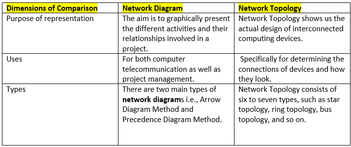
A Network Topology depicts how a network is physically connected. On the other hand, a network diagram is a graphical or visual representation of a system, including the dependencies and interaction between different activities. However, a Network Topology can be of two kinds i.e., physical network topology and logical/signal network topology.
The term network topology mainly concerns the use in computer networks to depict their interaction, while you can use the network diagram in general circumstances for operations management as well as home purposes. Every kind of industry, whether it be construction or software, uses the project scheduling or project management technique, including the use of network diagrams.
Whenever we talk about network topology, we are referring to the design and interaction of computer devices. The network topology helps to determine how the actual network looks like.
Symbols of Network Diagram
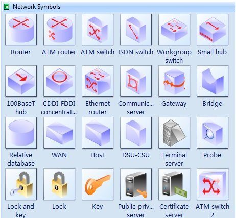
Here is a list of various symbols used in computer network diagrams, maps, schematics, etc. You can check their visuals along with the images given below.
- Network and Peripherals
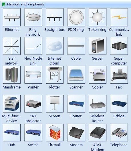
Given below are different kinds of network and peripheral symbols used in a network diagram.
- Straight Bus
It is an arrangement of LAN where every single node gets interconnected with the link or main cable called the bus.
- Ethernet
It serves as a basis for IEEE 802.3 standard that indicates the lower and physical software layers.
- Router
It is a device to forward data packets between computer networks to create an overlay internetwork.
- FDDI Ring
It is a standard in the local area network used for data transmission and uses optical fiber as the standard and underlying physical medium.
- Bridge
It helps to reduce the amount of data traffic and filter it at a network boundary on a LAN to divide it into two different segments.
- Star Network
It is a LAN where the central or main computer gets directly connected with all the nodes.
- Switch
This symbol gets used at a low-level network protocol layer to join multiple computers.
- Super Computer
The logo depicts the frontline computer with contemporary processing capacity.
- Mainframe
The symbol indicates the big computer.
- Hub
It joins the multiple devices together and forms a segment of a single network.
- Internet Cloud
It indicates the segregation point between the responsibilities of users as well as the network providers.
- Physical Devices Network Symbols
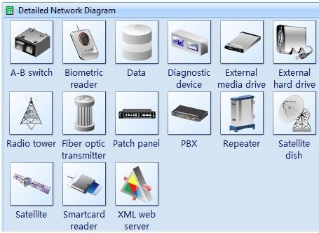
Given below are some network symbols to denote physical devices.
- Biometric Reader
It is the most common and popular symbol to show biometric security devices.
- XML Web Server
This network is for the special-purpose device for managing, securing, and mediating the XML traffic.
- A-B Switch
The device’s symbol is indicated to split the signal between antenna and cable or other inputs
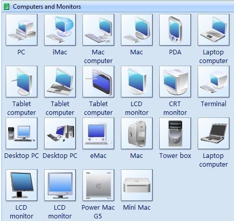
- Monitor and Computer Symbols
- Server Symbols

- Network Logical Symbols
Network Diagram Examples
To further clarify the concept, you should see the network diagram examples with their analysis given below.
- Network Security Diagram
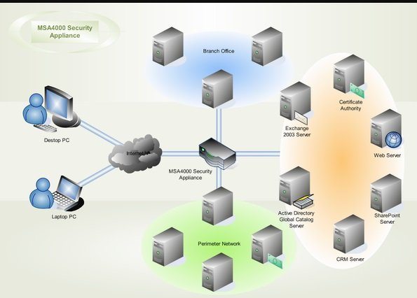
A network security diagram helps you map out the methods of security implemented in an organization to protect its assets. It shows how valuable information is protected while it is being transmitted and stored.
- WAN Network Diagram
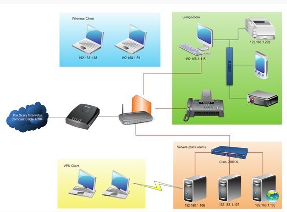
It is a large graphical presentation of a computer network spread across different states and countries. It will show how the components in different networks interact with each other.
- 3D Network Diagram
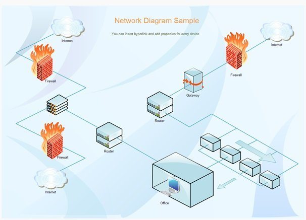
The 3D images enhance the effect and visual look of a presentation. It is a kind of schematic presentation to show the existing network diagram in a more specific manner. By drawing the 3D images, results will be much precise than the results shown in 2D models.
How to create a network diagram effortlessly with Edraw?
Creating network diagrams will be much easy and effortless process if we use software explicitly made for the purpose. One such best and high-performance tool we are going to review here is EdrawMax. It can help you create various diagrams such as flow diagrams, UML diagrams, Brainstorming diagrams, electrical diagrams, and much more along with the network diagrams. There are different shapes and templates already available to make attractive diagram designs.
You can try EdrawMax for free as it is available in Windows, Mac, and Linux versions. Read the following steps to know how to create a network diagram with Edraw.
- Step 1: Prepare by choosing a template.
After going for the free trial and launch of EdrawMax, you need to start as follows.
In the very first step, you have to select from 200 diagram types available with Edraw.
For the network diagram, select the icon ‘network diagram,’ then proceed with the following steps to create a network diagram.
- Step 2: Choose the type of network draw
From the panel of Network Gallery, choose one of your desired draw types to start creating the network diagram. You will also get an option to browse network diagram examples, which puts you at ease to drag and drop the symbol and make a network diagram.
Choose the connector tool in the Basic Tools group and connect the various network diagram shapes with the smart connector.


